This chapter describes the practical work that has been done so far in the research program, and the major problems encountered. A full description of the basis for this work can be found in chapter 3, Research Aims, and chapter 4, Program of Research.
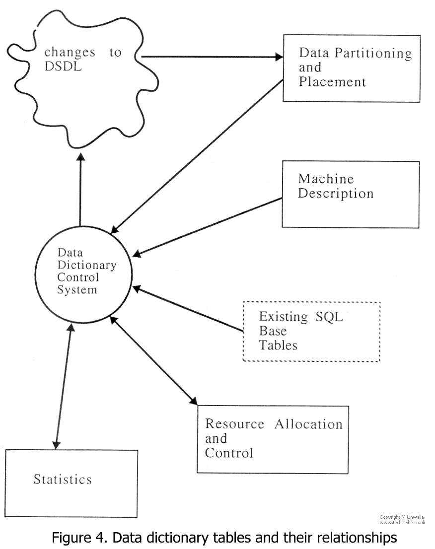
SQL2 defines (notional) Information Schema (IS) base tables that are used to define all the data (eg row descriptors of user data) and meta-data (eg Information Schema view descriptors, schema table descriptors, privilege descriptors, etc). one of the aims of the research is to describe Data Partitioning and Placement, Machine Architecture, Resource Allocation and Control, and Statistics (fig 4), in the DRAT machine in terms of extensions to the SQL Information Schema.
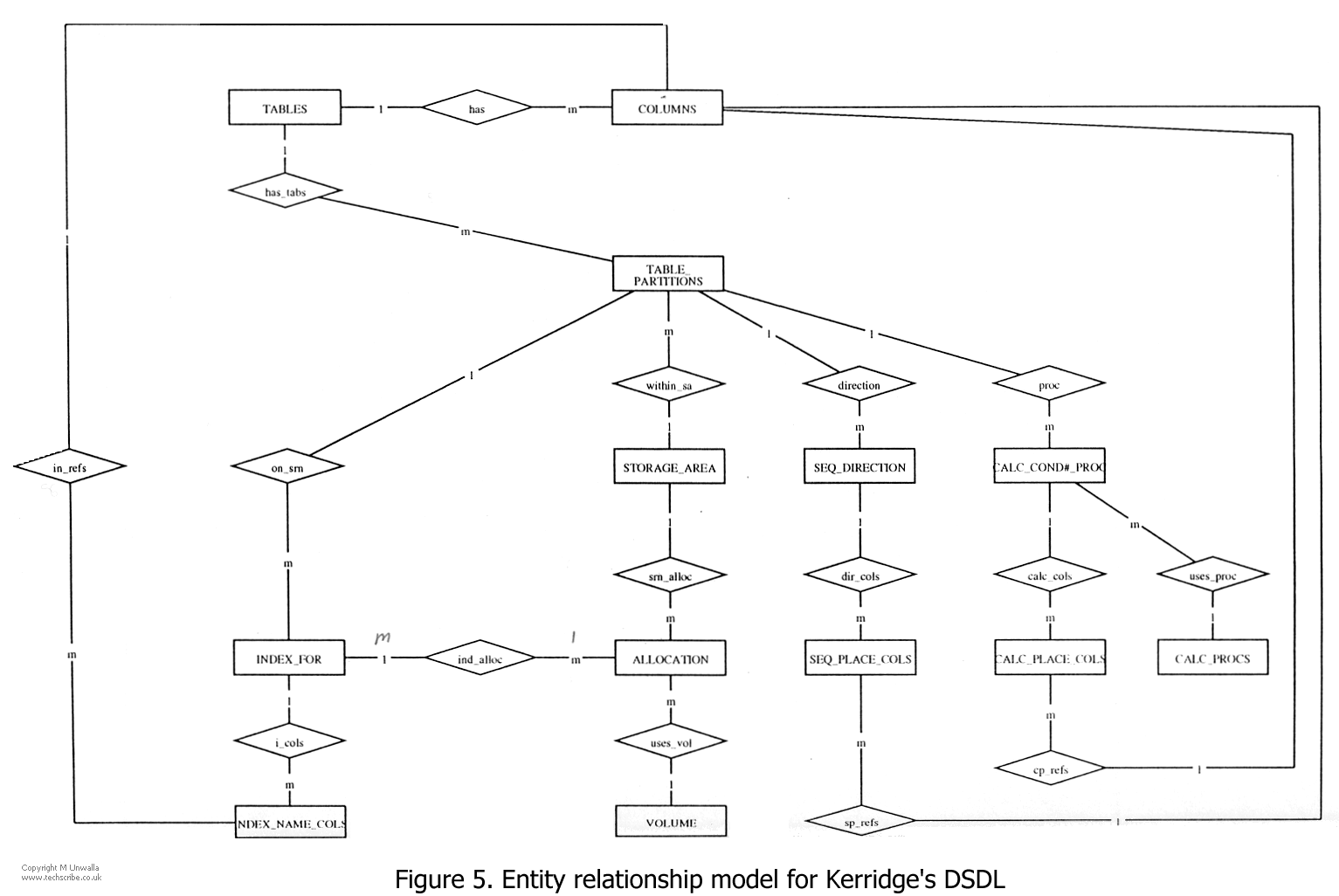
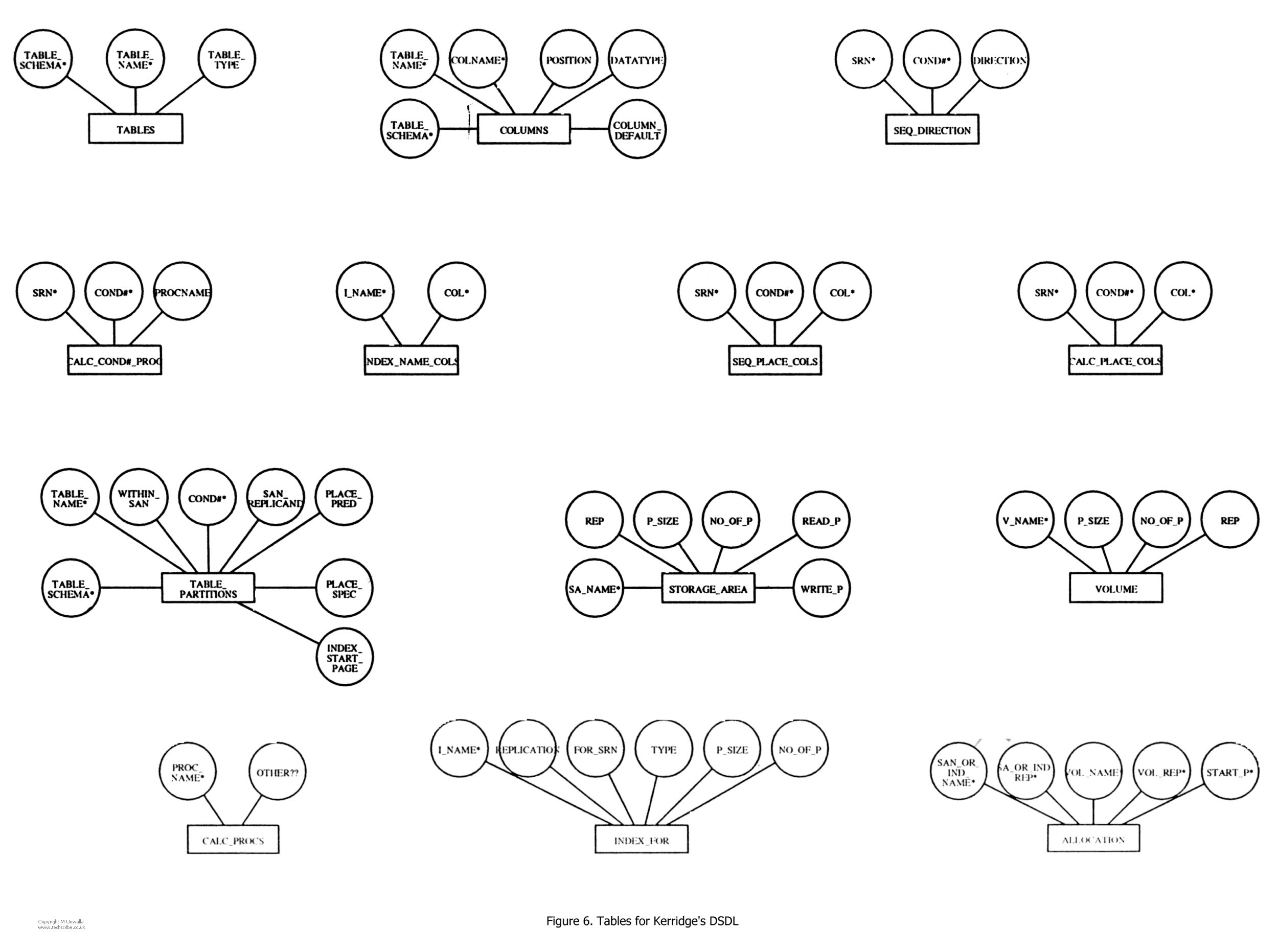
As far as the research itself is concerned, an ER model for Kerridge's DSDL has been produced (figures 5 and 6), which is believed to be correct. Tables produced from this ER model can reflect the information that is contained in Kerridge's DSDL, but further work is required to correct anomalies in the table designs of figure 6.
Machine Architecture, and Allocation and Control tables are currently being specified. Machine Architecture tables model the overall physical architecture (of the relevant portions) of the database machine (ie Relational processors, and Data Storage elements). Allocation and Control describes the current state of the machine. In particular, which Relational processors are being used. It may be necessary to sequence the use of these, if there are not sufficient for optimal concurrent usage. How best to do this is still under consideration.
Tables for Statistics will come later, and at this stage no details of the requirements are known.
Early on in the design stage, the use of Entity-Relation (ER) modelling in conjunction with the Software through Pictures (StP) CASE tool was adopted. StP has an ER diagramming tool, which generates Data Definition Language (DDL) statements for various languages, including SQL (ANSI version). It is also possible to produce a customised DDL format.
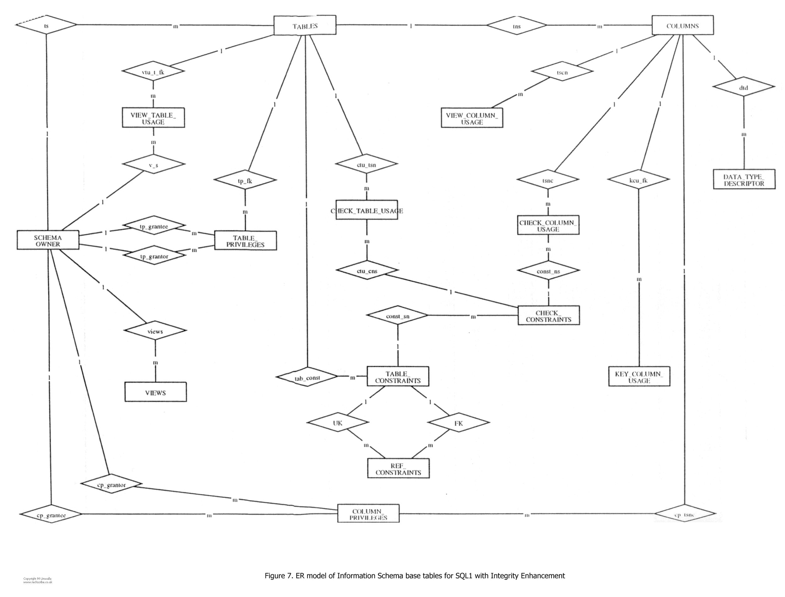
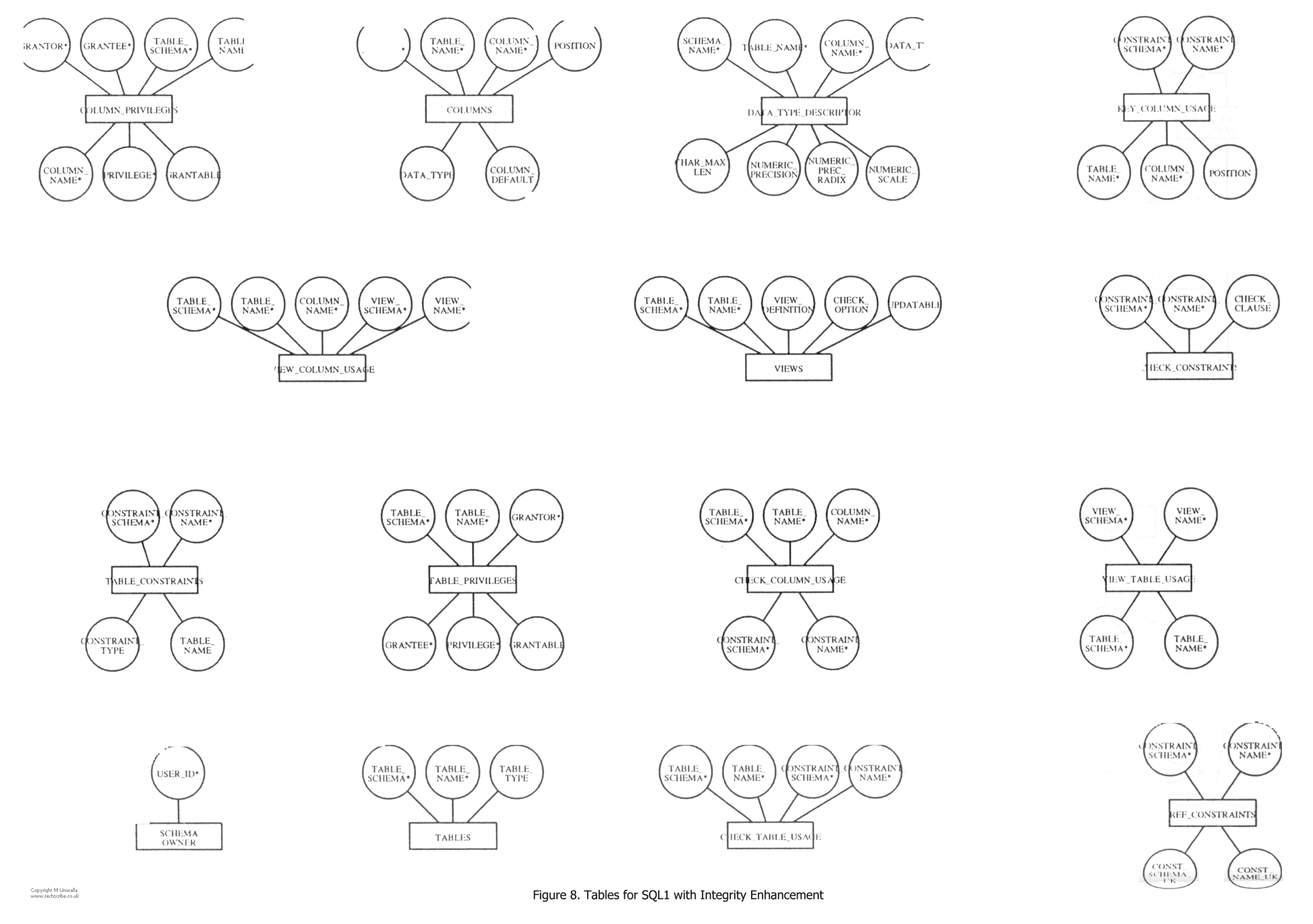
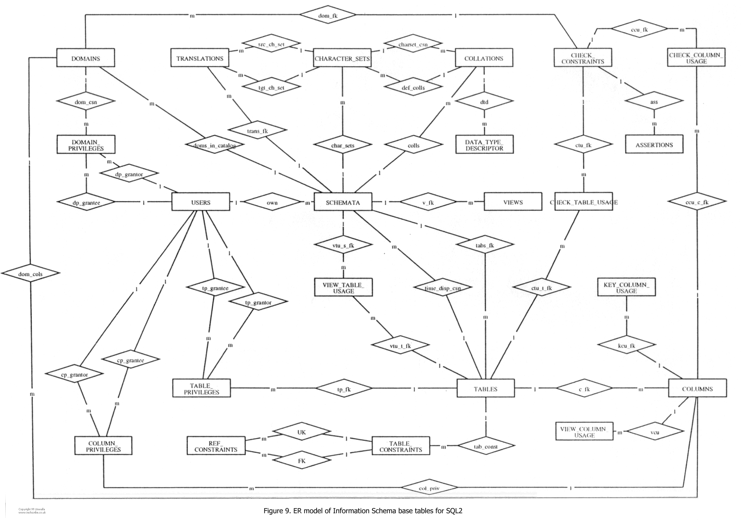
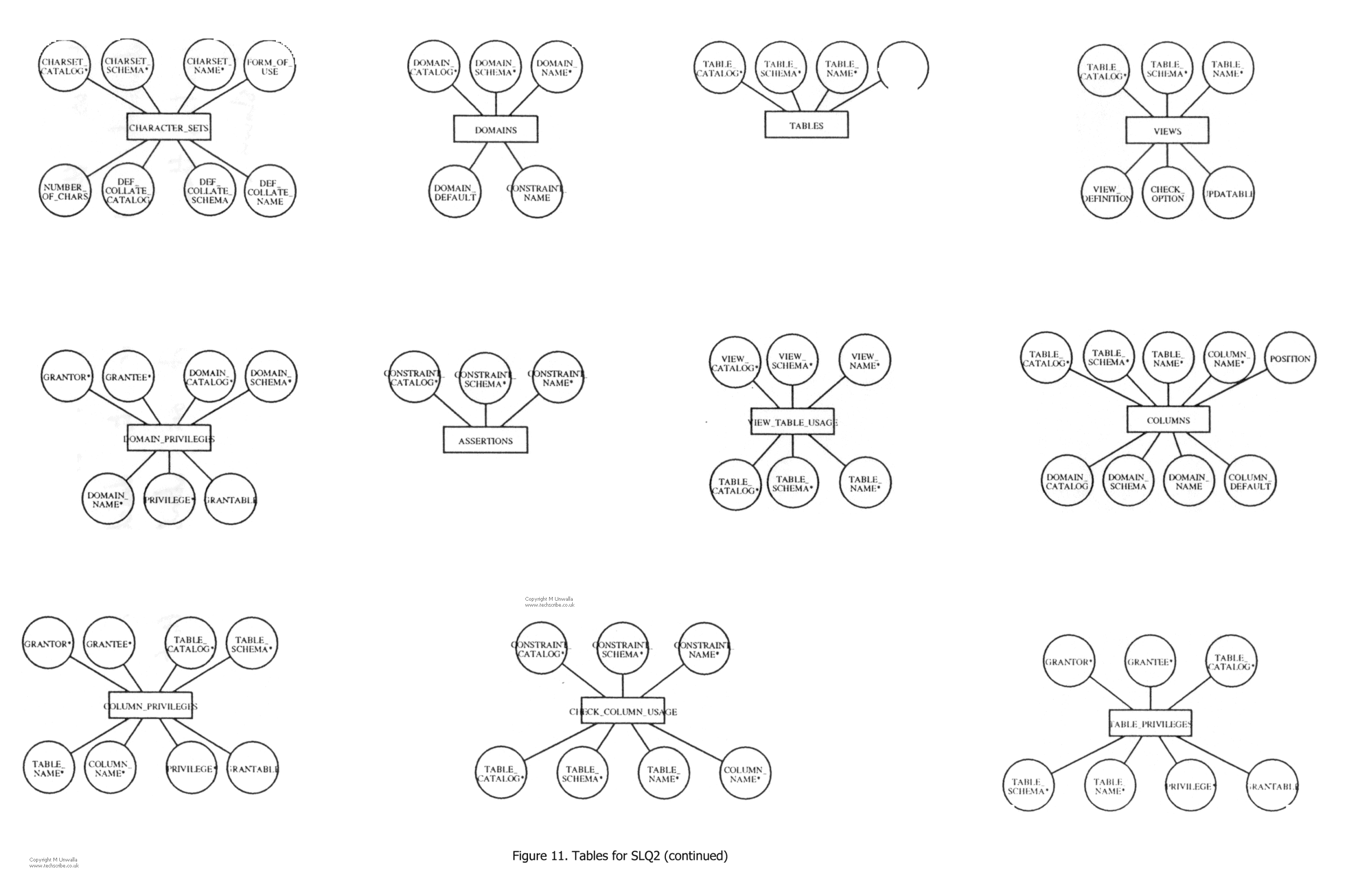
Since additional tables were to be added to the original SQL tables, the SQL Information Schema base tables were also modelled using Entity Relation diagrams. Both SQL1 with Integrity Enhancement [IS089] (figs 7,8), and SQL2 [IS090] (figs 9, 10, 11) have been described, although the reader should note that SQL1 does not explicitly have the concept of an IS.

A useful check of self-consistency is to produce an ER diagram from the SQL Information Schema tables, then generate a DDL from the diagram. The DDL code, when run, should produce tables that are exactly the same as those from which the ER diagram was first produced. (In our case, the DDL code itself should match the DDL code in the SQL IS). Apart from minor details, this self-consistency has been achieved with the SQL2 Information Schema tables, although in an indirect way (see 5.2.3).
Two major problems arose early on; the first was to decide on the nature of an 'entity', and the second was with the CASE tool itself.
A fundamental difficulty was to decide what would be described by entities, and what would be described by relations in the ER diagrams. The SQL2 Information Schema base tables could be looked upon as all being entities in their own right, in which case they could all be modelled as entities. On the other hand, since there are in essence two kinds of table - linker, and (for want of a better word) descriptor, one option was to model linker tables as relations, and descriptor tables as entities.
A decision was made to use the former option. The reason for this is that the SQL base tables are 'things in the real world' (even if only notional!) that we wish to describe. Therefore, to consider some as relationships, for whatever reason, is unappealing.
In entity-relation terms, a 'weak entity' is one which is identified by relationships with other entities [CHEN76, ELMA89]. In a relational database this would be a table in which a foreign key is contained within that table's primary key.
For example, consider a relational database with two tables; DEPARTMENT and EMPLOYEE. For simplicity, these are not shown in full. Departments have a unique department number (dep#), and employees have a unique number (emp#). Key attributes are underlined.
DEPARTMENT( DEP#, LOCATION, ...)
EMPLOYEE( EMP#, NAME, DEP#, ...)
     FOREIGN KEY DEP# REFERENCES DEPARTMENT
Now consider a situation in which within any department each employee has a unique number which, however, may be the same as another employee number in a different department.
EMPLOYEE( EMP#, NAME, DEP#, ...)
     FOREIGN KEY DEP# REFERENCES DEPARTMENT
The key of the relation is the combination of EMP# and DEP#. EMPLOYEE is partially identified by DEP#, and is known as a weak entity. In an ER diagram it would be drawn:
EMPLOYEE
All of the SQL2 base tables, except for table USERS, should be modelled as weak entities since part of each table's primary key is also a foreign key.
The StP Entity Relation Editor (ERE) does not support 'weak entities'. There is no method to deal with this from within the StP environment. Without the ability to specify weak entities, when a relational schema which contains these is produced, although attributes will be generated and shown as foreign keys, they will not be identified as part of the primary key of the referencing table.
In order to overcome this limitation of the CASE tool, a non-standard approach to ER modelling has been adopted. All attributes of all tables are included in the diagrams (normally, foreign key attributes are not shown, since they are implicit in the diagram). After generation of the DDL, The duplicated Foreign Key references are removed. The reason for taking this option was that it is the 'cleanest' that could be found.
StP has a small programming language that enables a user to specify the syntax of DDL code that is generated from ER diagrams. Unfortunately, it is not powerful, and is unsuitable for string manipulation. This leads to an inability to specify correct SQL2 syntax, and is the reason that the unwanted foreign key references mentioned above have to be removed manually. However, the conversion to a correct syntax is mechanical. Appendix B shows the StP DDL based on figures 9, 10, and 11; Appendix C is a modification of Appendix B, which shows the correct SQL2 syntax. The reader can see the correspondences in detail in these appendices, but for explanatory purposes, an example (FK_REFS_EXAMPLE) is given below (figs 12, 13). Figure 13a shows the code that is generated by StP from figure 12, and figure 13b shows its re-arrangement to conform to SQL2 syntax.

CREATE SCHEMA
AUTHORIZATION FK_REFS_EXAMPLE
CREATE TABLE PARTS
     (
     PART_NO         INTEGER,
     PART_SUPPLIER   CHARACTER,
     MORE_DETAILS    CHARACTER,
     PRIMARY KEY (PART_NO, PART_SUPPLIER)
     )

CREATE TABLE PROJECTS
     (
     PART_NO         INTEGER,
     PART_SUPPLIER   CHARACTER,
     PROJECT         CHARACTER,
     OTHER_INFO      CHARACTER,
     USED_IN_PART_NO         INTEGER,    Foreign Key from PARTS
     USED_IN_PART_SUPPLIER   CHARACTER,  Foreign Key from PARTS
     PRIMARY KEY (PART_NO, PART_SUPPLIER, PROJECT)
     )
Figure 13a. Code generated by StP from diagram 'fk-refs_example'
CREATE SCHEMA
AUTHORIZATION FK_REFS_EXAMPLE

CREATE TABLE PARTS
     (
     PART_NO         INTEGER,
     PART_SUPPLIER   CHARACTER,
     MORE_DETAILS    CHARACTER,
     PRIMARY KEY (PART_NO, PART_SUPPLIER)
     )

CREATE TABLE PROJECTS
     (
     PART_NO         INTEGER,
     PART_SUPPLIER   CHARACTER,
     PROJECT         CHARACTER,
     OTHER_INFO      CHARACTER,
     PRIMARY KEY (PART_NO, PART_SUPPLIER, PROJECT),
     FOREIGN KEY (PART_NO, PART_SUPPLIER) REFERENCES PARTS
     )
Figure 13b. Modified code conforming to SQL2 syntax
The problem of being unable to denote weak entities has now been acknowledged by IDE, and we have recently received object code (the program named 'gensch') which takes entities (annotated as 'weak'), and generates DDL schema correctly [WILS91]. This has not been evaluated yet.
Fortuitously, the non-standard approach to ER modelling that was adopted is beneficial to us, inasmuch as all the attributes that are needed for each table are clearly seen on that table, thus aiding comprehension.
Contents | 1 Introduction | 2 Review | 3 Research aims | 4 Program | 5 Work | References | Appendix A | Appendix B | Appendix C